


What is Alternating Current, and why do we need it?
Lets discuss some of the fundamentals of Alternating Current or AC. Historically Electrical usage was originally all Direct Current or DC. In fact most of our devices still use DC internally. However AC is much more efficient than DC for transmitting power over great distances. This is why we get AC delivered to an outlet and our device converts it to DC.
DC, in general is much easier, and less complex to use than AC, as alternating the flow of current can change the characteristics of even simple circuits. I want to look at some of the basic fundamentals of AC as they apply to a simple electric circuits.
Generating AC
To better understand AC, we will take a quick look at a simple visual example of an AC generator. The generator relies on the principle of magnetic induction. This means that when metal moves though a magnetic field, a electromotive force or voltage is induced in the metal. If the metal is a coil of wire connected to a load, the induced voltage will cause current flow.
The magnitude of the generated electricity is proportional to the motion of the coil through the magnetic filed, and the strength of the magnetic field. The direction of the coil in relation to the magnetic field determines the direction of current flow.

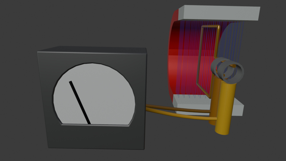
In our example when the coil is horizontal, or zero degrees rotational position, the voltage and current is zero. As the coil turns towards the magnet, it passes through the magnetic filed inducing a voltage and current flowing in one direction, based on the coil and magnet orientation. This reaches a maximum at 90 degrees.
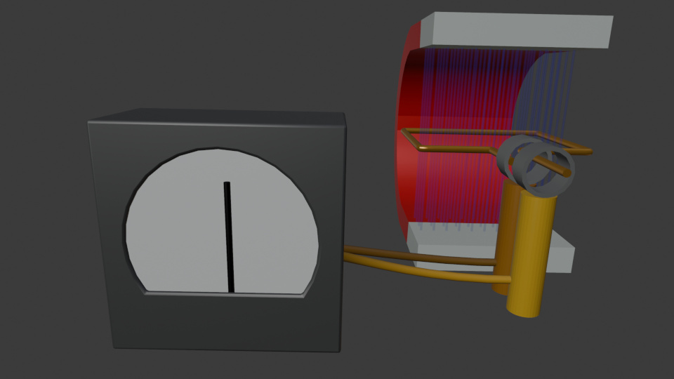
When the coil moves past 90 degrees, the voltage and current decrease back to zero at 180 degrees. The coil is now flipped from its original position. Continuing on towards 270 degrees the coil is now moving in the opposite direction through the magnitude field, therefore the voltage an current induced flow in the opposite direction.
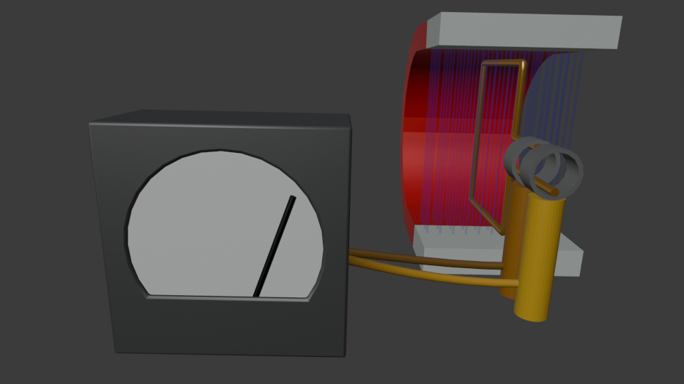
As the coil rotates back to its original position the voltage and current again drop to zero. This is known as a cycle. Standard household AC is 60 cycles per second or 60 hertz, meaning this process occurs 60 times a second.
The fluctuations of voltage and current are called a sign wave. And graphing a sing wave we can map out several important characteristics of AC.
Electrical Reactance
AC circuits are affected by impedance, which was not a consideration in DC circuits. Impedance is a combination of resistance and reactance, and is measured in ohms.
While resistance converts energy to heat, reactance stores electrical energy in the form of a magnetic field around a coil (inductive reactance), or as a change between the plates of a capacitor (capacitive reactance).
Since we are dealing with a simple circuit consisting of a load (resistor) and a power source, impenitence is not going to be a factor and I am not covering it in depth. Just be aware that it becomes a factor in more complex circuits.
AC Values and Consistency
One of the issues working with AC is that values like current and voltage fluctuate over time. This leads to several different methods of characterizing them. Consistency in presentaiton of data is of paramount importance when working with AC.
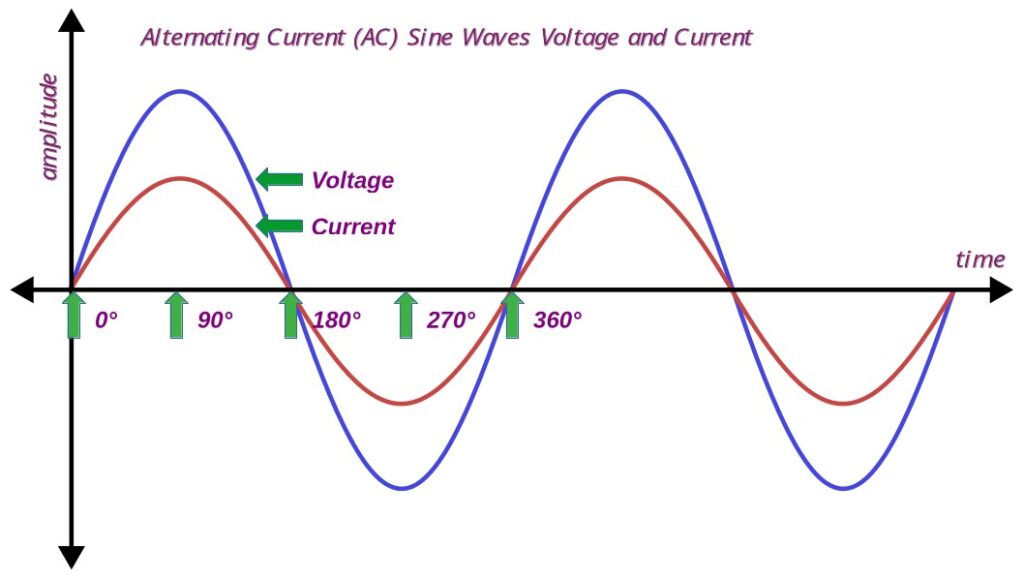
In the image above we see the AC sign wave. Note that sign waves are presented for current and voltage. However, since they measure different units, they are not compatible. They are presented here mainly for convince in that they are related.As per our generator example we can break a sign wave down into 360 degrees. Above you see the relationship at the 0, 90, 180, 270, and 360 degree points. This is one cycle.
AC is measured in Cycles Per Second which is designated as hertz. In America house hold AC is 60 Hertz. In Europe it is 50 Hz. So the single cycle repeats, in America, 60 times every second. So lets talk about various ways of representing the AC sign wave.
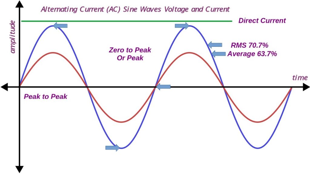
Direct Current
Direct current is just that. Which is why it is easier to work with. Generally voltage is constant at some level, and current varies depending on the load. If we want to know what the DC voltage is at any point in time, its the same. This can’t be said for AC.
AC Peak to Peak
peak to Peak is measured form the positive high point to the negative high point. It is basicly the total voltage swingfrom lowest value to highest value. Not very useful, except when determining a components maximum limits, or when advertisers want to make something sound impressive.
AC Zero to Peak
This value is measured form zero to one of the peaks. It is generally expressed as an unsigned number. It is used similarly to Peak to Peak. For example, one of the stations I was at back in my Coast Guard days advertised a transmit power of 2.5 Mega watts. This was Zero to Peak, and it was not on a sing wave. The actual power was a whole lot less.
AC Average
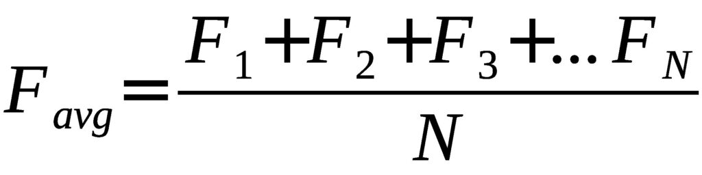
The above formula is used to calculate the average of a fluctuating value. You divide it up into small sections, add them up and divide by the number of sections. This is generally an absolute value, as in a sign wave the negative component would cancel the positivist component in a sign wave.
There is an easier way to arrive at this value. AC is a sign wave and the average value of a sign wave is always 63.7% of Zero to Peak.
AC RMS
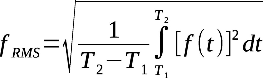
The above equation is for calculating RMS values. However, just like Average, if the sign wave is consistent, then the RMS value is 70.7% of Zero to Peak.
For example, in the US when I was growing up the outlet voltage was said to be 110. This is an average value. Later, it was decided that RMS was a better representation of true power, current, and voltage. So now the outlet voltage is 120V RMS.
Impedance and Reactance
In AC circuits there is both resistance and impedance. Resistance we looked at in DC circuits. Impedance, like resistance, is measured in ohms, but is made up of reactive components. Specifically capacitors and inductors.
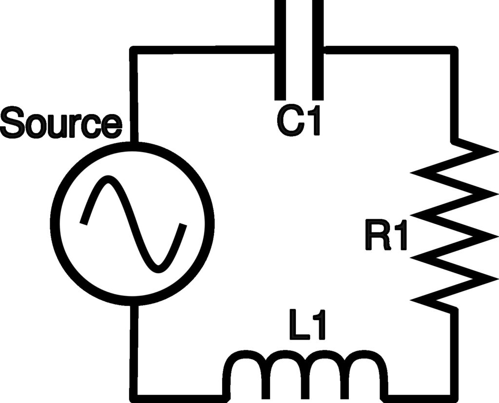
In the above circuit we have added, in addition to resistance (R1), a capacitor (C1) and an inductor (L1). These supply capacitive (farads) and indcuctive (henery’s) reactance. Looking at the equations for inductive and capacitive reactance, we can see they are the inverse of each other.
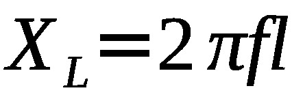
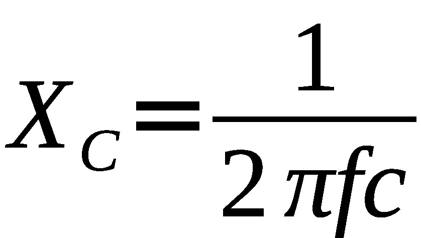
Note that reactance, and therefore impedance, is dependent on frequency (f). While this adds complexity to AC circuits, it is very useful in certain fields. For example the only time I made real use of these equations was during a period when I was designing various filters (notch, band pass, low pass, and high pass).
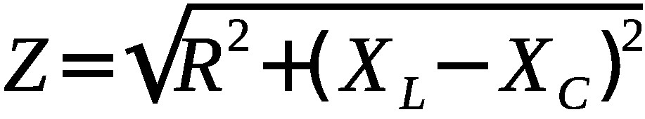
In an AC circuit impudence is derived from the square root of the squares of both resistance and reactance.
if we remove the reactive components (inductor and capacitor) from the basic circuit, we can analyze it as we would a DC cirucit. We just need to be constant with our units. Peak to Peak (pp or p-p) and zero to Peak (p or 0-p) are not to useful. And today you will be more liely to use Root Means Square (rms) over Average (avg). We just need to be consistent. If we use Vrms, then we need to use Irms. if we use Vavg, we need to use Iavg.
Conclusion
Today, for the most part, we don’t really work with alternating current much anymore. But there are occasions, as most houses are wired with AC these days, And understanding AC circuits can help troubleshoot the unusual problem or two that always seems to crop up. For example, there was a carport light that filckered when the switch was off. It took a basic understanding of AC to understand why that was happening and rectify the problem. Another issue I that understanding AC cirucits helped me with was flucuating power in the 120V outlets (230V is the standard in the Philippines). Of course that also involved understanding the Country Electrical code and figuring out what the contractor had done. But an understanding of AC circuits helped.
Leave a Reply